Inductive Proof Graphs
If we want to formally prove that a system satisfies some safety property (i.e. an invariant), we can do this by finding an inductive invariant. An inductive invariant is a particular type of invariant that is at least as strong as the target invariant to be proven, and is also inductive, meaning that it is closed under all transitions of the system.
For example, for a formal specification of the two-phase commit protocol, we may want to establish the core safety property stating that no two resource managers can end up in conflicting commit/abort states:
\[\small \newcommand{\stext}[1]{\small\text{#1}} \begin{align*} &TCConsistent \triangleq{} \\ % A state predicate asserting that two RMs have not arrived at \\ % conflicting decisions. \\ &\hspace{1cm}\forall rm_i, rm_j \in RM : \neg (rmState[rm_i] = \stext{ABORTED} \land rmState[rm_j] = \stext{COMMITTED}) \end{align*}\]A possible inductive invariant for establishing this property (along with its formal proof in TLAPS) may look like the conjunction of the following smaller, lemma invariants and the top-level safety property:
Upon inspection, it is relatively straightforward to observe that these individual lemmas establish various important facts/invariants about the protocol. In this form, though, it is still quite difficult to understand the logical structure of such an inductive invariant and how it represents the correctness argument for establishing the top-level safety property, \(TCConsistent\).
Instead, we can view inductive invariants through the lens of an inductive proof graph, a graph structure that explicitly represents the compositional dependency structure of an inductive invariant. We can do this by breaking down the logical structure of a inductive invariant like the one shown above stated as a single, monolithic conjunction of lemmas.
Specifically, for any inductive invariant of the form
\[Ind = S \wedge L_1 \wedge \dots \wedge L_k\]each lemma in this overall invariant may only depend inductively on some other subset of lemmas in \(Ind\). More formally, for a system \(M=(I,T)\), with transition relation \(T\), proving the main induction step for such an invariant requires establishing validity of the following formula
\[\begin{align} (S \wedge L_1 \wedge \dots \wedge L_k) \wedge T \Rightarrow (S \wedge L_1 \wedge \dots \wedge L_k)' \end{align}\]This can be decomposed into the following set of independent proof obligations:
\[\begin{align} \begin{split} (S \wedge L_1 \wedge \dots \wedge L_k) &\wedge T \Rightarrow S' \\ (S \wedge L_1 \wedge \dots \wedge L_k) &\wedge T \Rightarrow L_1' \\ &\vdots \\[0.1em] (S \wedge L_1 \wedge \dots \wedge L_k) &\wedge T \Rightarrow L_k' \end{split} \end{align}\]With this in mind, if we define \(\mathcal{L} = \{ S, L_1, \dots, L_k\}\) as the lemma set of \(Ind\), we can consider the notion of a support set for a lemma in \(\mathcal{L}\) as any subset \(U \subseteq \mathcal{L}\) such that \(L\) is inductive relative to the conjunction of lemmas in \(U\) i.e.,
\[\left( \bigwedge_{\ell \in U} \ell \right) \wedge L \wedge T \Rightarrow L'\]As shown above, \(\mathcal{L}\) is always a support set for any lemma in \(\mathcal{L}\), but it may not be the smallest support set. This support set notion gives rise a structure we refer to as the lemma support graph, which is induced by each lemma’s mapping to a given support set, each of which may be much smaller than \(\mathcal{L}\).
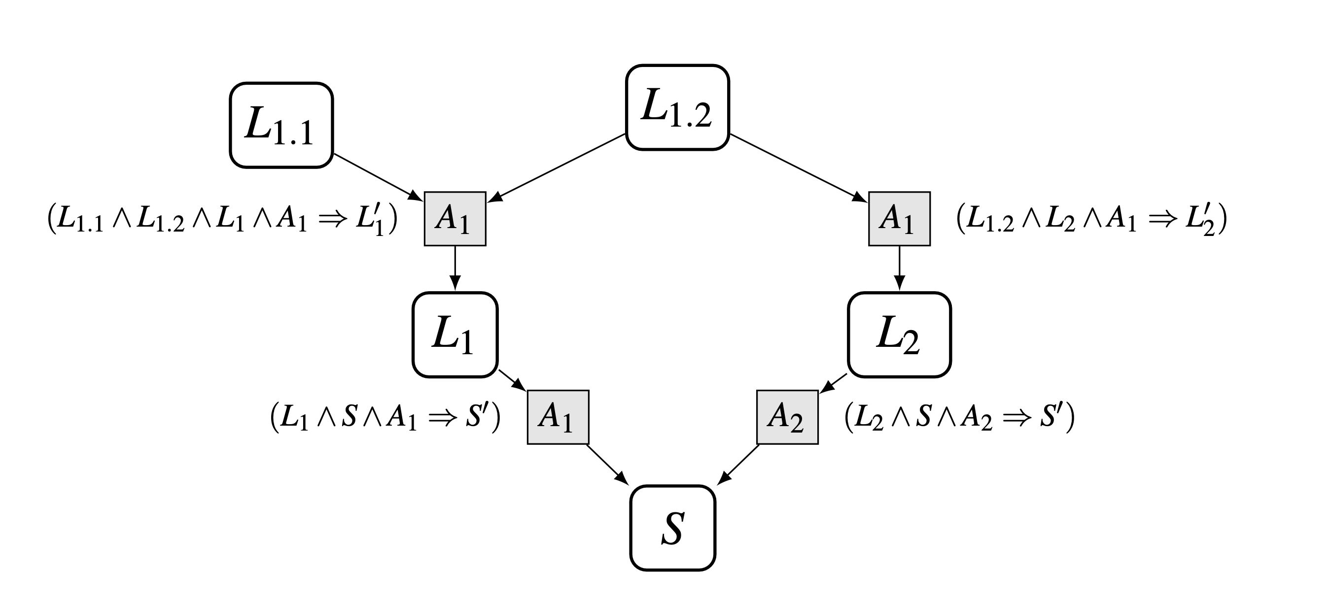
For distributed and concurrent protocols, the transition relation of a system \(M=(I,T)\) is typically a disjunction of several distinct actions i.e., \(T=A_1 \vee \dots \vee A_n\). So, each node of a lemma support graph can be augmented with sub-nodes, one for each action of the overall transition relation. Lemma support edges in the graph then run from a lemma to a specific action node, rather than directly to a target lemma. Incorporation of this action-based decomposition now lets us define the full inductive proof graph structure. The following figure shows an example of an abstract inductive proof graph along with the corresponding inductive proof obligations at each node.

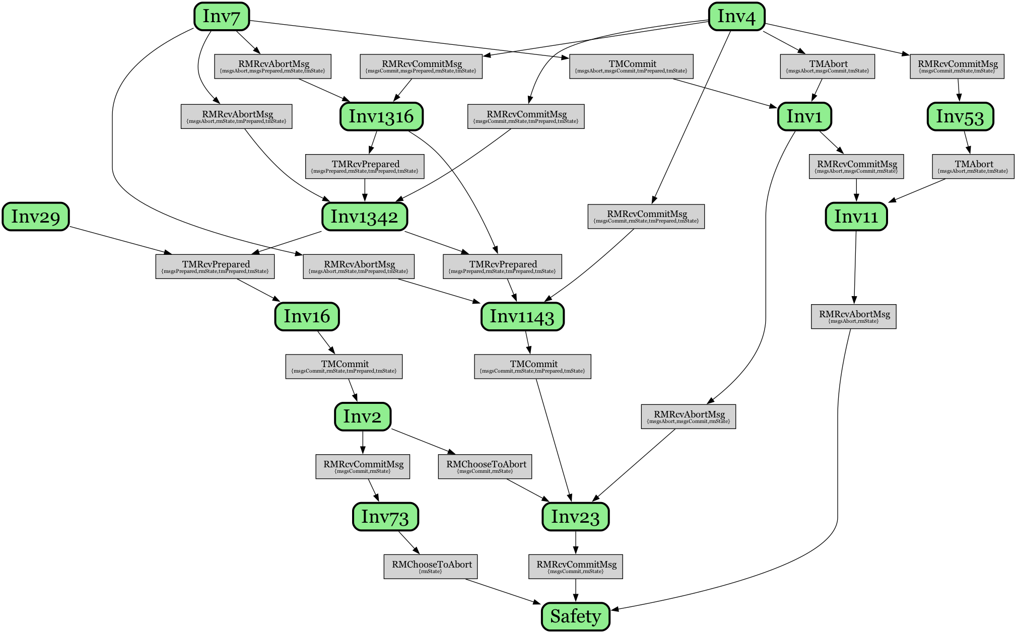
More concretely, the following is an inductive proof graph for the two-phase commit protocol specification that corresponds to the inductive invariant for establishing \(TCConsistent\) from above:

Green nodes represent individual lemma invariants, gray nodes represent actions of the protocol, while edges show the induction dependencies between them. For example, \(Inv11\) supports the top level safety property via the RMRcvAbortMsg action, stating that
\[\small Inv11 \triangleq \forall rm_j \in \text{RM} : (\langle \stext{Abort} \rangle \in msgsAbort) \Rightarrow (rmState[rm_j] \neq \stext{COMMITTED})\]That is, if an abort message has been sent, then no resource manager can be in a committed state. The preservation of this invariant is sufficient to prevent violation of the safety property \(TCConsistent\) via some RMRcvAbortMsg action, since it ensures no abort messages can be present in the system if some resource manager has already committed.
We can trace the lineage of this lemma logically backward, to its own two support lemmas:
\[\small \begin{align} Inv53 &\triangleq \forall rm_i \in \text{RM} : (tmState = \stext{INIT}) \Rightarrow \neg(rmState[rm_i] = \stext{COMMITTED}) \\ Inv1 &\triangleq (\langle \stext{Abort} \rangle \in msgsAbort) \Rightarrow (\langle \stext{Commit} \rangle \notin msgsCommit) \end{align}\]The first, \(Inv53\), prevents the presence of any committed resource managers in the initial state. Similarly, \(Inv1\) ensures that presence of an abort message in the system precludes the presence of a commit message, since this could lead to a resource manager then becoming committed.
Finally, both of these lemmas, \(Inv53\) and \(Inv1\), are then supported by
\[\small \begin{align} Inv7 &\triangleq (tmState = \stext{INIT}) \Rightarrow (\langle \stext{Abort} \rangle \notin msgsAbort) \\ Inv4 &\triangleq (tmState = \stext{INIT}) \Rightarrow (\langle \stext{Commit} \rangle \notin msgsCommit) \end{align}\]which ensure that, initially, no commit/abort messages can be present in the system.
Variable Slices
Note that an additional feature afforded by the compositional structure of these inductive proof graphs is the notion of variable slices. That is, at each individual node of the proof graph, we can statically determine a subset of state variables that are relevant for support lemmas needed to discharge that node. This variable slice is determined based on a static analysis of the lemma and action node pair. In the graph above, action nodes are annotated with their variable slices below.
For example, for the RMRcvAbortMsg action of the \(Safety\) lemma node, the variable slice is \(\{msgsAbort, rmState\}\), meaning that any support lemmas required to discharge this node need only refer to those state variables. This can be seen in its single support lemma, \(Inv11\), for example, which refers to exactly those state variables.
These variable slices are useful both for automated inductive invariant inference and also for human guided development, since they provide a formal way to focus attention on, ideally, a small subset of relevant state variables. With monolithic representations of inductive invariants as shown above, it is often unclear which variables are relevant for a given lemma/action pair, making this reasoning task burdensome.
Cyclic Proof Graphs
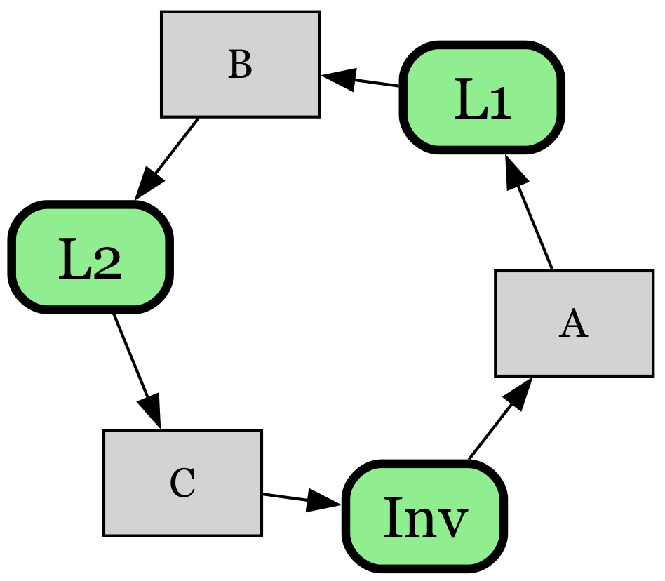
Note that the definition of proof graphs do not imply any restriction on cycles in a valid inductive proof graph. As a simple example of a cyclic proof graph, consider a simple “ring counter” system with 3 state variables, \(a,b\), and \(c\), where a single value gets passed from 𝑎 to 𝑏 to 𝑐 and exactly one variable holds the value at any time. A basic formal specification of such a system is as follows:
\[\small \begin{align*} &\text{VARIABLES } a,b,c \\ \\ &\text{Init } \triangleq a = 1 \land b = 0 \land c = 0 \\ \\ & A \triangleq a > 0 \land b' = a \land a' = 0 \land \text{UNCHANGED } c \\ & B \triangleq b > 0 \land c' = b \land b' = 0 \land \text{UNCHANGED } a \\ & C \triangleq c > 0 \land a' = c \land c' = 0 \land \text{UNCHANGED } b \\ \\ &\text{Next } \triangleq A \lor B \lor C \\ \\ &\text{Inv } \triangleq a \in \{0,1\} \quad \text{(* top-level invariant. *)} \\ \\ & L1 \triangleq b \in \{0,1\} \\ & L2 \triangleq c \in \{0,1\} \end{align*}\]An inductive invariant establishing the property \(Inv\), that 𝑎 always has a well-formed value (e.g. always either 0 or 1), will consist of 3 properties that form an induction cycle, each stating that 𝑎,𝑏 and 𝑐’s state are, respectively, always well-formed. Using \(Ind = Inv \wedge L_1 \wedge L_2\) works as such an inductive invariant, since it establishes that all of \(a,b,c\) are in valid states. The inductive proof graph for \(Ind\), shown below, is a pure cycle containing these 3 lemma nodes:

Comparing Inductive Proofs
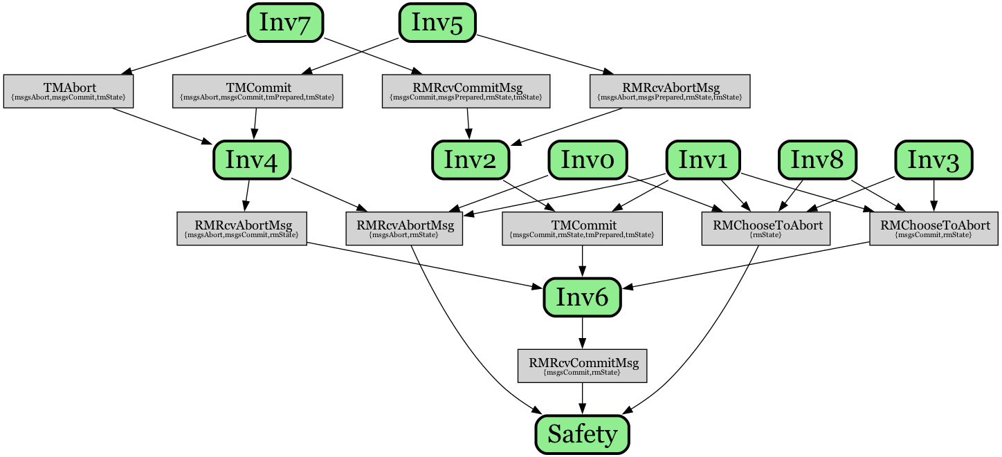
These proof graphs also provide a more principled way to compare different inductive invariants for proofs of the same protocol and property. For example, consider the following, alternate inductive proof graph for establishing the \(TCConsistent\) property of the two-phase commit protocol (along with TLAPS proof), that was originally generated by an automated inductive invariant inference tool:
\[\small \begin{align*} Safety &\triangleq TCConsistent \\ Inv6 \,\, &\triangleq \forall rm_i \in \text{RM} : ([type \mapsto \stext{Commit}] \in msgsCommit) \Rightarrow (rmState[rm_i] \neq \stext{aborted}) \\ Inv0 \,\, &\triangleq \forall rm_i \in \text{RM} : (rmState[rm_i] = \stext{COMMITTED}) \Rightarrow ([type \mapsto \stext{Commit}] \in msgsCommit) \\ Inv1 \,\, &\triangleq \forall rm_i \in \text{RM} : (rm_i \in tmPrepared) \Rightarrow ([type \mapsto \stext{Prepared}, rm \mapsto rm_i] \in msgsPrepared) \\ Inv8 \,\, &\triangleq \forall rm_i \in \text{RM} : ([type \mapsto \stext{Prepared}, rm \mapsto rm_i] \in msgsPrepared) \Rightarrow (rmState[rm_i] \neq \stext{working}) \\ Inv3 \,\, &\triangleq ([type \mapsto \stext{Commit}] \in msgsCommit) \Rightarrow (tmPrepared = \text{RM}) \\ Inv4 \,\, &\triangleq (\neg([type \mapsto \stext{Abort}] \in msgsAbort) \lor (\neg([type \mapsto \stext{Commit}] \in msgsCommit))) \\ Inv2 \,\, &\triangleq \forall rm_i \in \text{RM} : ((rmState[rm_i] = \stext{PREPARED}) \lor (\neg([type \mapsto \stext{Prepared}, rm \mapsto rm_i] \in msgsPrepared) \lor (\neg(tmState = \stext{init})))) \\ Inv7 \,\, &\triangleq ([type \mapsto \stext{Commit}] \in msgsCommit) \Rightarrow (tmState \neq \stext{init}) \\ Inv5 \,\, &\triangleq ([type \mapsto \stext{Abort}] \in msgsAbort) \Rightarrow (tmState \neq \stext{init}) \end{align*}\]

This overall inductive invariant is more succinct (fewer total lemmas), but it is not immediately clear how it relates to the first inductive invariant from above. The lower level lemmas \(Inv7\) and \(Inv5\) correspond to the lemmas \(Inv7,Inv4\) from above, but various other lemmas in the structure are quite different.
Note that some aspects of these proof graphs are independent of the choice of lemmas in the graph e.g. the nontrivial incoming action nodes for \(Safety\) will always be the same, for any possible inductive invariant. In this proof graph, though, for example, the \((Safety,RMChooseToAbort)\) node support is quite different, consisting of 4 supporting lemmas:
\[\small \begin{align*} Inv0 &\triangleq \forall rm_i \in \text{RM} : (rmState[rm_i] = \stext{COMMITTED}) \Rightarrow ([type \mapsto \stext{Commit}] \in msgsCommit) \\ Inv3 &\triangleq ([type \mapsto \stext{Commit}] \in msgsCommit) \Rightarrow (tmPrepared = \text{RM}) \\ Inv1 &\triangleq \forall rm_i \in \text{RM} : (rm_i \in tmPrepared) \Rightarrow ([type \mapsto \stext{Prepared}, rm \mapsto rm_i] \in msgsPrepared) \\ Inv8 &\triangleq \forall rm_i \in \text{RM} : ([type \mapsto \stext{Prepared}, rm \mapsto rm_i] \in msgsPrepared) \Rightarrow (rmState[rm_i] \neq \stext{working}) \\ \end{align*}\]The variable slice, though, states that we need only to constrain the \(rmState\) variable for this support lemma set. From these 4 support lemmas, however, it turns out that we can deduce the relevant fact about \(rmState\), which matches \(Inv73\) from above. That is, we can infer the following from the 4 lemmas above via implication (equivalent to \(Inv73\) above):
\[\small \forall rm_i \in \text{RM} : (rmState[rm_i] = \stext{COMMITTED}) \Rightarrow (rmState[rm_i] \neq \stext{working})\]In this case, it seems that even though the overall inductive invariant is smaller, the structure of the proof graph is arguably less interpretable, and less similar to a proof thay may be developed by a human that was guided by this structure explicitly.
Conclusions
At a high level, these proof graphs essentially make explicit the kind of backward, inductive reasoning that is applied when trying to show correctness of a safety property. That is, we work backwards via protocol actions, finding invariants that must hold true in prior steps in order for the system to always be safe with respect to some target property in question.
In some ways, we may also view these proof graphs as one way of marrying the inductive invariants used for formal verification with the kind of semi-formal, pen and paper proof structures often written by humans. For example, a careful induction proof in a distributed systems paper may implicitly resemble this kind of structure (e.g. see the Raft dissertation proof). These inductive proof graph structures provide a useful way to make this formal, while also showing that these types of graph structures can be seen as ultimately equivalent to any (monolithic) inductive invariant.
These graph structures are also concretely exploited for automated inductive invariant inference in this work, and for improving the interpretability of the inductive invariant development process. They also bear similarities to the inductive data flow graphs discussed here.